

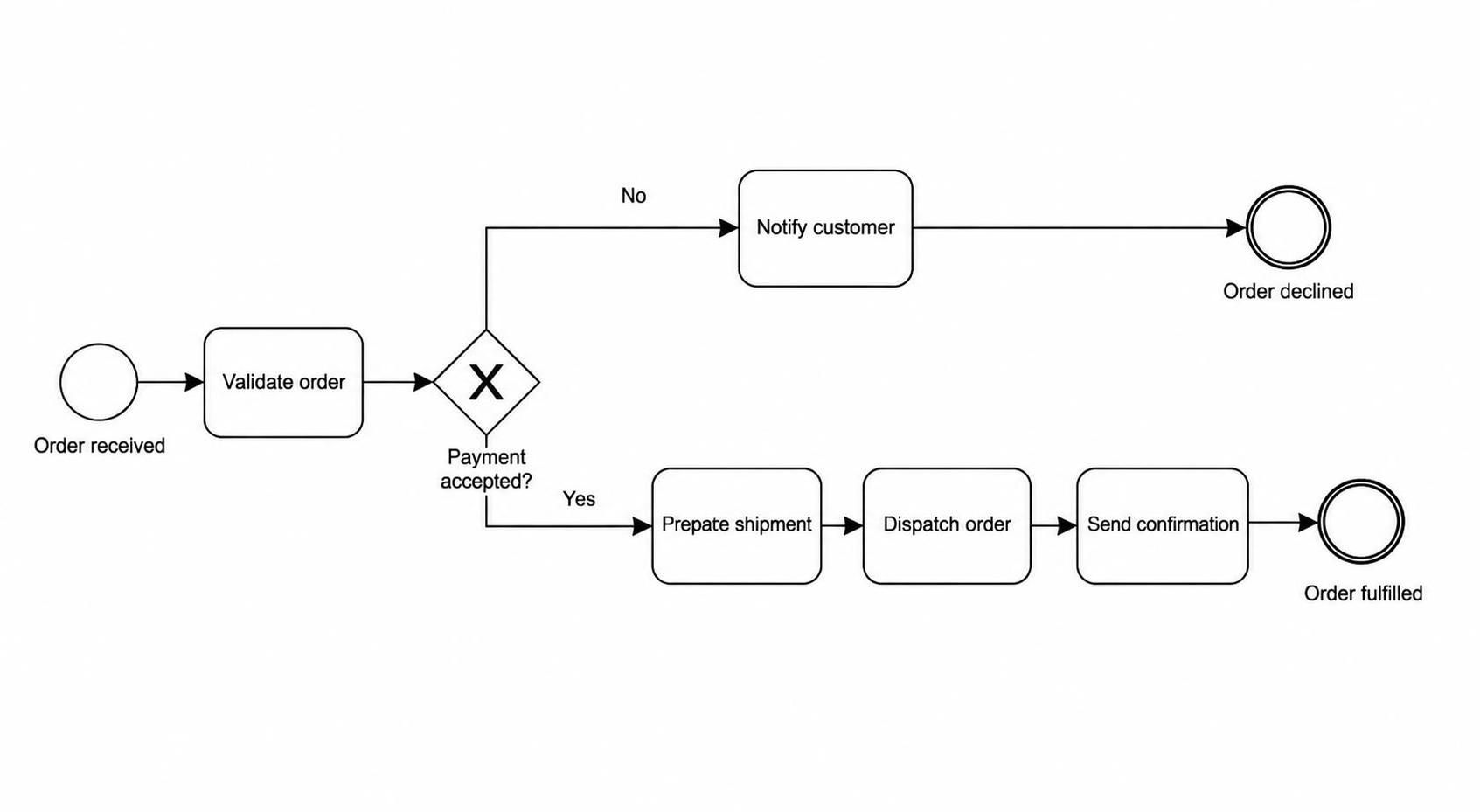
In the world of business process management, clarity is currency. The diagram presented here serves as a foundational example of how to visualize a critical business scenario: Order Fulfillment. By translating a real-world sequence of events into a structured visual flow, organizations can identify bottlenecks, define automation logic, and ensure all stakeholders share a common understanding of the workflow.
This tutorial will dissect the architecture of this process, explaining the significance of each BPMN (Business Process Model and Notation) element and how to apply these concepts using modern tools like Visual Paradigm.
Deconstructing the Process Architecture
At its core, this diagram represents a linear process with a single, critical decision point. It moves from a state of receipt to either a state of fulfillment or a state of rejection. Let’s break down the components that make this logic work.
1. The Trigger: Start Event
The process initiates with a Start Event, depicted as a thin-lined circle. In this context, the event is labeled “Order received.” In BPMN, this is the signal that a new instance of the process has entered the system. Without a clear start event, the process logic has no entry point.
2. The Core Activity: Validate Order
Following the start, the system performs a Task (represented by a rounded rectangle) labeled “Validate order.” This represents the first step of processing the incoming data. It implies that the system is checking the order details against business rules before proceeding further.
3. The Critical Logic: The Exclusive Gateway
The most complex part of this diagram is the Exclusive Gateway (the diamond shape with an ‘X’). This is the decision node that branches the process flow based on specific conditions. The text “Payment accepted?” acts as the condition for the branches.
- Logic: The system must choose one path out of the available options. It cannot proceed down both “Yes” and “No” paths simultaneously for a single order instance.
- Branches: The arrows exiting the gateway are labeled “Yes” and “No,” explicitly defining the conditions required to traverse that specific path.
4. The Outcomes: End Events
Every process must have a termination point, known as an End Event (double-lined circle). This diagram features two distinct outcomes:
- Order declined: If the payment gateway rejects the transaction, the flow moves to the “Notify customer” task and then ends.
- Order fulfilled: If the payment is accepted, the flow moves through the fulfillment sequence (“Prepare shipment,” “Dispatch order,” “Send confirmation”) and ends with a successful state.
Why This Modeling Matters
The power of this diagram lies in its simplicity and its ability to highlight dependencies. As noted in the source text, the modeling question is not “How many symbols can we use?” but rather “Which details matter to the people who will review, improve, or implement this process?”
By visualizing the decision point early, stakeholders immediately understand that fulfillment depends on payment acceptance. This prevents the implementation of a shipping workflow that attempts to ship orders before money has been secured.
Extending the Model: From Concept to Detail
While this diagram is excellent for a high-level overview, a production-ready system often requires more granularity. Here is how you might expand this model using Visual Paradigm’s advanced features:
- Swimlanes: You could introduce lanes to separate the “Customer,” “Sales System,” and “Warehouse” to clarify who is responsible for each task.
- Message Events: Instead of a simple task, the “Payment accepted?” check could be modeled as a Message Event, simulating a callback from an external payment gateway.
- Timers and Exceptions: A real-world diagram might add a timer to handle orders that stall in “Prepare shipment” or an exception path for items that are out of stock.
Summary
This Order Fulfillment flow demonstrates the essential elements of process modeling: a clear start, a logical sequence of tasks, a conditional decision point, and defined outcomes. Whether you are using Visual Paradigm for enterprise architecture or a simple diagramming tool, adhering to these structural principles ensures your business processes are both human-readable and machine-actionable.